You may wish to skip my “editorial notes” and go directly to the original article. And I welcome comments.
Editorial Notes: 07/19/2024: R-Pods are showing up everywhere and with so many new owners, Facebook groups are becoming an important resource for many to learn about their R-Pods (such as R-Pod Owners and for me, RPod 171 Owners Club). And many questions are posted about how to add Solar. If you found your way to this epistle, you may have seen my Comments on one or more posts on those FB Groups.
Our story began back in 2010 with an RP-177. That was before the industry began producing “plug and play” solar panels with built-in charge controllers and the so-called “solar ready” campers. You may (probably will?) choose to do something simpler than I’ve done, but I hope that you will find some of the “principles” that I present worth considering.
If I may, I would like to editorialize:
- The Charge Controller: As you will see in Design Choices and Experiences, knowing the actual watts from the solar panels and the actual watts consumed from the batteries gives me the total picture of what I’m doing to the battery. Thus I can manage the gozinta -and- gozouta and know in advance where I stand with available power from the batteries.
- Mounting the Panels: Mounting panels on the roof makes no sense to me (even ‘tho I camp in the southwest/New Mexico, where seldom can we locate the R-Pod in any kind of shade). The 20’ of wire (or more) allows me to insure that I get the most benefit from the sun.
- A generator?: No thanks. We purchased one, carried it once or twice, but — too much hassle and noise. We’ve gotten along fine with batteries and solar panels, even spending weeks at our cabin site .. building our straw-bale cabin. (See BTW below.)
- Help from the Dealers?: It seems dealers are happy to see the R-Pod leave their lots, without much attention to introducing the buyer to its features, how to care for it, etc. And FR doesn’t offer much help beyond the product sheets for installed appliances, etc. Thus buyers (often of used R-Pods as well) are left to trying to figure out how to operate and care for their campers. An example is “solar ready” (see Solar Ready RV? What Does That Mean? for another’s view on this topic).
BTW: We never (hardly ever?) connect to “shore power” even if it is available at a campsite. Propane serves to heat (cabin heat when needed, hot water, cooking) and to cool (fridge). We have adopted a principle: we heat or cool -nothing- with battery (these are a -very inefficient- uses of 12 volt DC). As for air conditioning – we camp in the southwest, usually above 5,000 feet elevation, so nights are cool, humidity is low, and we are outside hiking during the day. I empathize with those of you at lower elevations and more humid climates.
Another Note, 10/23/2023: In a further attempt to provide information useful for others considering adding solar panels for their RV, or information to help plan and manage their power system, I’ve added a section reflecting my Real World Experiences.
A Note, 8/22/2023: So many questions about “Solar” and “Solar Ready” – a great description of the latter: Solar Ready RV? What Does That Mean? AND … a really great tutorial for those who aren’t already into “electricity”, particularly the DC power integral to our RVs and solar systems.
Outline
- Introduction
- Background
- Experience
- Highlights
- Design Choices
- Solar Panel
- Charge Controller
- Batteries
- My Present System (RP-171)
- Installation
- Materials
- Tools
- Charging On The Road (work in progress)
- Real World Experiences
- Three Day Camping Trip, July 2023
- Battery Maintenance in Storage, October 2023
- Power Utilization
- Summary
Introduction
Background: There are almost as many schemes for setting up a solar system for a camper as there are people who have campers. Some are very simple – batteries, a charge controller, and a solar panel. Others are quite sophisticated with large capacity batteries, a large capacity charge controller, many watts of solar panels, a large capacity inverter (to deliver 120 volt AC for microwave/convection oven, air conditioner, and other ‘conveniences’), and a means of tracking charging and usage. I am on my 2nd configuration, this for a new 2023 RP-171 that is replacing a 2011 RP-177 that we enjoyed for 13 years.
Here is my approach: keep it simple, have enough capacity so that I don’t need to be anxious about running out of 12 volt electricity, and an ability to monitor power into and out of the battery (amp hours and/or watt hours) . We don’t need much electric power – lights, controllers for refrigerator and water heater, CPAP machine, and at times the bathroom and heater fans. Ninety percent of our camping is off-grid – National Forest or BLM campgrounds, occasionally a dispersed camping site, and for a few years, at our cabin site while we were building the cabin (and before we got the cabin’s solar system up and running).
Experience: From my experience, here is a summary of the “capacity” that we have needed:
- For the RP-177 we used 300 to 500 watt hours (WH) per day, or about 25 to 40 amp hours. (I set up a monitoring system that measured and recorded solar amps into and out of the battery, so this is -real world- data from our experience).
- We were judicious in how we used battery power: nothing “heated” with battery power, only lights, fans (bathroom vent and heater), charging “devices” (phones, tablets, occasionally a laptop), and a CPAP machine. And nothing is “cooled” with battery; the absorption fridge uses heat to cool, so we do not run it on DC but rather on propane (tho it uses a small amount of DC power for it’s control circuit).
- We got along fine with a 70 watt solar panel, a Morningstar SunSaver MPPT 15 amp charge controller, and 2 GC-2 6-volt deep cycle batteries (~230 amp hours total, at 12 volts or ~2,750 watt hours).
- For our new RP-171, I’ve set up with a 100 watt solar panel, a Victron SmartSolar MPPT 20 amp charge controller, and for now 2 SRM-24 12 volt deep cycle batteries (~160 amp hours or ~1,920 watt hours).
Highlights: There are as many configurations as people who have crafted a solar setup for their RV as there are owners of RVs. Here is overview of the the system for the RP-171; details to follow:
- Solar panels: adequate power production (watts), easy to handle (weight & size)
- 100 watts, 20 x 26 inches folded, 8 pounds
- Charge controller: efficient, adequate capacity (watts), monitor amps in and amps out, configurable
- MPPT, 20 amps (240 watts), monitor solar amps and battery amps with smartphone app via Bluetooth, settings to adapt to specific battery requirements
- Battery: adequate capacity
- 2 each SM24 Deep Cycle batteries, 80 amp hour each for a total of 160 amp hours (80 amp hour usable; battery life is reduced when more than half of it’s capacity is used).
Go to Outline or Top
Design Choices
Solar Panels: Considerations for the solar panels included capacity, size, and location.
- Capacity – The 70 watt panel I used on the RP-177 provided sufficient amp hours to keep the battery charged for our normal use. I would typically be able to get more than 4 hours of sunshine, sometimes as much as 8 hours (250+ watt hours to as much as 500+ watt hours per day). This was usually more than our use of battery power.
- Size – Keys here are .. where to store it when on the road and ease of handling (reason to follow). I store it in the rear storage area of the R-Pod which requires it be no more than 30″ wide to fit through the door. As for handling – since it is not to be mounted permanently I wanted to be able to move it “effortlessly”.
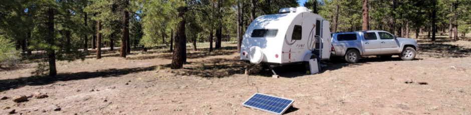
- Location – We park in a shady area when available – it was therefore important that the panel be portable. With 10′ or 20′ feet of extension cord, I am able to locate the panel where it will get the maximum sun for the longest time (and move it as the sun moves).
Charge Controller: My criteria for a charge controller was 12 volts with charging capacity to handle up to 300 watts of solar panels. And I would use only an MPPT controller; PWM controllers dispose of up to 30% of output from the panels. MPPT controllers are more expensive, but it is either go with MPPT or get more panels (watts) with PWM.
A feature that I wished for – a means of tracking solar input and battery output. For the RP-177 I had used a pair of monitoring devices that reported battery voltage, amps and watts being used real time, and the accumulation of watts over time. They were connected in such a matter that one measured power into the battery and the other power out of the battery. Thus I could monitor the gozinta-gozouta real time, and monitor and record cumulative watt hours in and watt hours out, day-by-day.
Special –Important– Note: It appears in some ads that one can charge a battery by simply connecting a solar panel, without a charge controller. Tis my view – this is not a good idea. Charge controllers manage power delivered to the battery with two important features: they adjust voltage for various stages of battery condition to optimize charging and battery life, and they limit current to avoid damage to the battery. A solar panel will deliver power at a constant rate and at what is often an inappropriate voltage. You can read more here.
Batteries: Type, cost, and weight were primary considerations.
- Standard Flooded Lead Acid (FLA) Deep Cycle batteries: Thirteen years ago, as a practical matter (availability and cost) these were the only batteries available.
- Only batteries classified as Deep Cycle are designed to provide relatively constant supply as opposed to auto “starting” batteries which need to deliver high amperage for a short time – as when starting a motor.
- The SRM-24 is a relatively inexpensive battery, used in many applications. Since they are 12 volt batteries, capacity can be increased by adding a 2nd battery, connecting them in parallel to combine their capacities.
- Because of the location of the batteries on the tongue of the R-Pod, a significant amount of any added weight is transferred to the towing vehicle. This can become a problem when towing with other than a large vehicle (I tow with a Toyota Tacoma with towing package).
- Three other considerations for FLA batteries: maintenance, useful capacity, and useful life.
- The level of electrolyte in each cell of the battery must be monitored to insure that it never drops below the top of the plates. If low, distilled water must be added or damage will be incurred limiting capacity, even the ability to charge, and useful life..
- Normal use of the battery should be limited to 50% of the rated capacity. So for a pair of SRM-24 Deep Cycle batteries rated at 160 amp hours, usage should be limited to 80 amp hours from a full charge.
- Discharging a battery to “empty” will certainly reduce both capacity and useful life, and may make the battery unable to take any significant charge.
- Useful life varies on many factors, but with good care can be expected to be a few years (our first set of GC-2 batteries required replacement after 7 or 8 years).
- Other Lead Acid batteries: Other types of lead-acid batteries are available, such as AGM. They have disadvantages similar to FLA, but do offer the advantage that they are sealed and monitoring electrolyte is not necessary. They are still subject to the 50% limit.
- Lithium-ion batteries (LiFePO4 are the most common): These are available and are now practical considering cost, performance, and weight.
- Many people are switching to LiFePO4 batteries. Prices have made them reasonably affordable.
- They offer advantages of 1) one can use the full capacity, 2) they are light weight, 3) they require virtually no maintenance, and 4) can be expected to have a much longer useful life than FLA.
- They have the disadvantage of requiring adjustments to the charge controller to match the chemistry of LiFePO4 which is different than FLA batteries. Or one may purchase a charge controller that is set up specifically for LiFePO4 batteries.
- And what may be a disadvantage for some – charging them when their temperature is below freezing will irreparably damage them.
- Many people are switching to LiFePO4 batteries. Prices have made them reasonably affordable.
My Present System
Solar Panel: I have started with one ECO-WORTHY 100W Portable Solar Panel. It is foldable: 26 x 20 x 2.8 inches, unfolds to 26 x 40 x 1.5 inches — very manageable. It comes with MC4 connectors, a standard among solar panels. I use 2-pin SAE “quick connectors” for my extension cords and camper connection, so I purchased additional MC4 connectors onto which I spliced an SAE connector.
- For the do-it-yourselfers: I could tell you which connection in the MC4 should be connected to which wire on the SAE connector. But I recommend using a voltmeter to determine which connection in the MC4 positive (+). Then select an SAE connector that has the red wire coming from the enclosed socket (not the bare pin), and connect that red wire to the + connection in the MC4. (May I add here: a voltmeter will be instrumental in many situations that require troubleshooting electrical systems, and especially when making any modifications like adding additional USB charging ports.)
Note: I’ve seen reports that SAE connectors are installed on some models of “solar ready” R-Pods. That is convenient, but I’ve also read that the wiring is set up with positive ground, the opposite of the more common negative ground. Before using the built-in wiring, check yours (see note above about use of a voltmeter). If it is positive ground, get an adapter cable that reverses the polarity. See the reference Solar Ready RV? What Does That Mean? for more info.
Mentioning connectors >> for the extension cable, I purchased about 20 feet of 12 gauge flexible cable and spliced SAE connectors on each end. An SAE connector was also installed at the trailer with wire going to the charge controller. Follow the description for the MC4-to-SAE splice: select the SAE connector for the wire coming from the source voltage to the enclosed socket of that connector.
 Charge Controller: I was very pleased with the SunSaver MPPT, having used Morningstar charge controllers at our cabin (1,000 watts of solar panels, 24 volt battery system). However it became inoperative in the move to the RP-171 (my bad). For the replacement, after much research and consternation, I chose the Victron SmartSolar MPPT charge controller. It can handle up to 20 amps, or 240 watts, of solar input. Key in my decision – it provides a monitoring function, reporting real-time and a daily history of cumulative amps and watts from the solar panel to the controller and the controllers output to the battery – that takes care of monitoring the gozinta to the batteries.
As for gozouta? The Victron controller has a Load connection (as do many controllers); it will provide constant 12 volt power directly from the charge controller. And the controller’s monitoring function will report output to the Load. Because our use of 12 volt power is small, less than the 20 amps that the controller can handle, I moved the primary 12 volt supply wire for the R-Pod from the battery and connected it to the Load connection on the charge controller. Now I can monitor both gozinta -and- gozouta.
Batteries: One Interstate SRM-24 battery came with the camper (I soon discovered that it had “gone bad”). I purchased 2 new Interstate SRM-24s and a dual-battery case, installed them on the platform at the back of the tongue, and wired them in parallel for a capacity up to 160 amp hours.
Important Note: To get full service life from a flooded lead acid (FLA) or AGM battery, they should never be drawn below half of their capacity. So I have 80 ampere hours of useful service (that figures out to be 960 watt hours: 12v x 80ah = 960wh).
I have considered switching to lithium batteries (lighter, greater capacity, carefree) but doing so will require changing the parameters in the charge controller and I would have to deal with freezing temperatures. I have experience with FLA batteries, so I will stick with them for now – possibly change when these near end-of-life.
UPDATE, 03/15/2025: Last fall the bank of FLA batteries at the cabin reached end-of-life. I chose to invest in LiFEPO4 batteries as replacement. Since they are installed in an otherwise unheated space, I insulated the “power system pit” (hole in the ground), added a temperature controlled switch (‘thermostat’), and small low power heating pads placed beneath the batteries. The ‘thermostat’ turns on the heating pads when the temperature in the “pit” drops below 40 F.
With this experience with the LiFEPO4 batteries, when I replace the batteries on the R-Pod I intend to again use the ‘thermostat’, but I will connect it between the solar panels and the charge controller. Then set the ‘thermostat’ to disconnect the solar panels when the temperature drops below 40F, thus preventing charging that would damage the batteries.
Installation:
First step was to settle 2 SRM-24 batteries in the battery tray. Then connect the 2 batteries together, wired in parallel with positive and ground connected to the battery nearer the master battery switch. And then, connect the positive (red) and negative (black) wires from the Master Disconnect Switch to the batteries.
Next, installation of the charge controller. Because the Victron is not weather proof, I chose to mount it inside the R-Pod, under the settee to port (yeah, I sailed small boats for many years so port is the left side of the boat, er R-Pod). This required running a wire from the Victron to the batteries .. and a wire-pair to an SAE connector outside the R-Pod for the solar panels.
- I drilled two holes from underside into the interior, just behind the front cross member near the exits for existing wires, large enough for a 3/8″ vinyl tubing caulked in place with silicon caulking.
- I then ran a wire from the input for solar panels on the Charge Controller, through one of the holes. On the other end just outside the R-Pod I mounted an SAE connector, providing a connection solar panels.
- Next I switched power for the R-Pod from a direct connection to the R-Pod’s interior, to the Load connection on the Charge Controller. I removed the wire from the positive terminal of the battery, cut off the ring terminal, and rerouted it into the R-Pod through the vinyl tubing and to the Load connection on the Charge Controller. (It is this reconfiguration that allows me to monitor usage of battery power on the Victron.)
For a simpler setup, I have seen an example where the Charge Controller was mounted in a weather proof box which was in turn mounted near the battery. I preferred to keep electronics internal to the R-Pod, plus doing so fit into future plans.
Note: As part of the reconfiguration, I disabled the R-Pod’s converter by switching it’s circuit breaker to the off position. The converter is normally used when ‘on-grid’ to provide power to the 12 volt circuits of the R-Pod and .. to recharge the batteries. But in my configuration, it’s voltage would now be an -input- to the Load connection on the charge controller. Since my setup is intended to satisfy all recharging requirements and to do so in a way that is optimum for the batteries, the converter is extraneous (and its voltage may even damage the charge controller).
One gotcha – the capacity of the output from the charge controller is insufficient to power the electric tongue jack. In the interim, I used the hand crank and I may even replace the electric jack with a manual jack. To have the convenience of the electric jack, I have run a new wire from the electric jack directly to the positive terminal of the battery. I removed the original wire from the post in the electric jack, insulated the ring connector with tape (keeping for future possible use), and connected the new wire from the battery in its place.
Materials (Links are to the materials that I purchased)
- 2 Interstate SRM-24 Deep Cycle Batteries (12 volt, FLA, deep cycle, 81 AH each)
- Local Interstate battery dealer. Also, many are pleased with WalMart batteries.
- Dual Type 24 Battery Box
- Local RV dealer or auto parts store or Camco Double Battery Box
- Charge controller
- 100 watt solar panel
- 2 each – 10 feet 12 gauge flexible wire, 1 black, 1 red
- At local big-box store or 12 Gauge Silicone Wire 10 ft red and black …
- Crimp Terminals
- Blue 1/2″ crimp ring terminals (for connections to the battery)
- Blue 3/8″ crimp ring terminals (for connection to the tongue jack)
- Blue crimp butt splice connectors (to adapt MC4 to SAE connectors)
- At local big-box store or Amazon
- SAE connectors
- 3/8″ or 1/2″ heat shrink tubing (to encase the splices between SAE connector and extension cable)
- At local big-box store
- 20′ of 12 or 14 gauge wire (for the extension cord)
- At local big-box store
- 6″ of 3/8″ vinyl tubing or similar, for thru-floor path for wires
- A dab of silicon caulking
Tools
- Wire cutter and electrical wire stripper
- Crimping tool (use a professional tool to get secure connections)
- Small screwdriver (for connections to the charge controller)
- Drill and 1/2″ or 5/8″ twist drill bit
On the Road
This topic is in work. It will describe modifications that I made to overcome limitations of the standard approach for charging the R-Pod’s battery from the Tacoma’s alternator/battery system.
Real World Experiences
July 2023, Camping: We spent 3 nights camping near Cumbres Pass in southern Colorado, in a National Forest campground at 10,000 feet elevation, no hookups.
- Batteries were topped off when we set up camp (charged enroute, another story).
- On arrival our 100 watt ECO-Worthy Solar Panel was set up to be in direct sun for as much of the day as possible. I oriented it towards sunrise in the morning, towards sunset after noon. I set the angle so it would be perpendicular to the sun at mid-morning and again at mid-afternoon.
- We are judicious about use of power: heat nothing with electricity (use propane or a butane cook top on the picnic table), use only LED lights, and limit our use of fans (bath or heater). But … the water pump draws 2.4 amps (30 watts), the absorption fridge needs power for its controller (.4 amps, 5 watts), I -do- use a CPAP when sleeping, and we recharge our various devices (phones, tablets, EPIRBS, and reserve battery for devices, which together can add up to a significant use of power).
Note: Click on the images to enlarge them, <back> on your browser to return to the text.
 Using the Victron Charge Controller, I’m able to monitor performance of our electric power system on my cellphone. The image on the right is a report of recent history during the camping trip:
- The vertical bar graph reports watt hours from the solar panels during the stages of charging: amount of time in bulk, absorption, and float.
- Having time in the Float stage is an indication that the battery is fully charge.
- The Solar Panel table displays data on the performance of the solar panels.
- The Battery table shows maximum and minimum voltages during that day.
- Because I’ve connected power for the R-Pod to the Load connection on the charge controller, the Consump. table reports actual utilization for the day.
For the two full days that we were in camp (“Yesterday” and “2 days ago”):
- The solar panel produced 370 and 450 WH during those days of full sun.
- We used 340 and 380 WH.
- Conclusion: The solar panel delivered all that we used, plus what was needed for battery maintenance (absorption and float modes), and more that wasn’t needed because the battery reached full charge and went into Float stage.
- And the system didn’t use all that was theoretically available: I estimate that at full power the panels had the capacity to produce 768 WH (88 watts for 6 hours, 50 watts for 4 hours, 20 watts for 2 hours).
October 2023, Battery Maintenance in Storage: Having seen many questions on the R-Pod Facebook groups about energy utilization, specifically battery power, 1) over a period of time I tracked the record of charging the battery and 2) I recorded power use by each of the devices in the R-Pod. These recordings are provided from the Victron charge controller via the smartphone app.
Charging Record: The record began with ~50% State of Charge (SOC). In storage, I use a 20 watt solar panel for maintaining the batteries. The panel is typically in full sun for 6 hours per day. The master battery switch was in the Off position so no load was placed on the battery from the R-Pod during this time.

The Graph 1 on the right shows a month’s worth of charging data. From the 25th day to the 12th day, the panel’s power was applied to bringing the battery up to 100% SOC. Beginning on the 13th day the battery was fully charged so charging was in bulk stage for a period of time, then briefly in absorption, then in float for the remainder of the day.

This Graph 2 provides greater detail for the 2 days before and 2 days after reaching 100% SOC. The panels produced yields of up to 100 watt hours (WH). For days 14 and 13; all of it went to increasing SOC (bulk stage). Then on days 12 and 11 bulk stage was in effect for a short time, then absorption for a very short time, then into float stage for the remainder of the day, basically maintaining SOC.

Graph 3 covers days 3 to ‘today’. Like Chart 2 it shows the stages of charging along with statistics of solar panel and battery condition. And I’ve expanded “yesterday’s” data to show the amount of time in each stage and the percent of solar watts delivered to the battery.
Power Utilization: To better manage power utilization, and judge how much is needed for various activities, I turned on each of the 12 volt devices in turn and recorded the power being used. (The 2022 RP-171 has LED lights throughout). Using these figures and the amount of time each “consumer” is operating, one can get a good estimate of power utilization in watt hours.
| Turned "On" | Power (watts) | Current (amps) |
| Nothing | 1 | 0.1 |
| Other (like with Nothing) | 1 | 0.1 |
| Water Heater | 4 | 0.3 |
| Bath Fan | 4 | 0.3 |
| Fridge | 5 | 0.4 |
| One Ceiling Light | 5 | 0.4 |
| Sansui Television (DC) | 30 | 2.4 |
| Radio | 6 | 0.4 |
| Furnace Fan | 27 | 2.1 |
| Water Pump | 30 | 2.4 |
| Inverter | 15% |
Summary:
- A 20 watt solar panel will easily maintain a battery at 100% SOC (I started with a 10 watt panel – it was inadequate). It will take a long time to re-charge a battery.
- With the Solar Panel and Battery data (bar graphs and tables) I can track gozinta and gozouta and monitor SOC, day by day.
- With the Power Utilization data, I can better manage our use of battery power.
- Having the data from the Victron Charge Controller gives me tools to monitor power available, power being used, and power being gained from the panels. This leads to confidence that we will have the power we need, or information to manage gozinta and gozouta.
 For reference, here is a chart of State of Charge (SOC) for lead acid batteries.
George Young (hiking@pngyoung.com)
Albuquerque, NM
August 16, 2023
Updated October 23, 2023
Updated July 19, 2024
This page to date: 1,229 views.
Hi,
This is very helpful! I would like to share it with someone who does not use Facebook. Can you please email a copy to me? Thank you.
Good afternoon, Darlene,
Sure, I will send it to your eAddress ovyn@comcast.net.
cheers,
george